Introduction
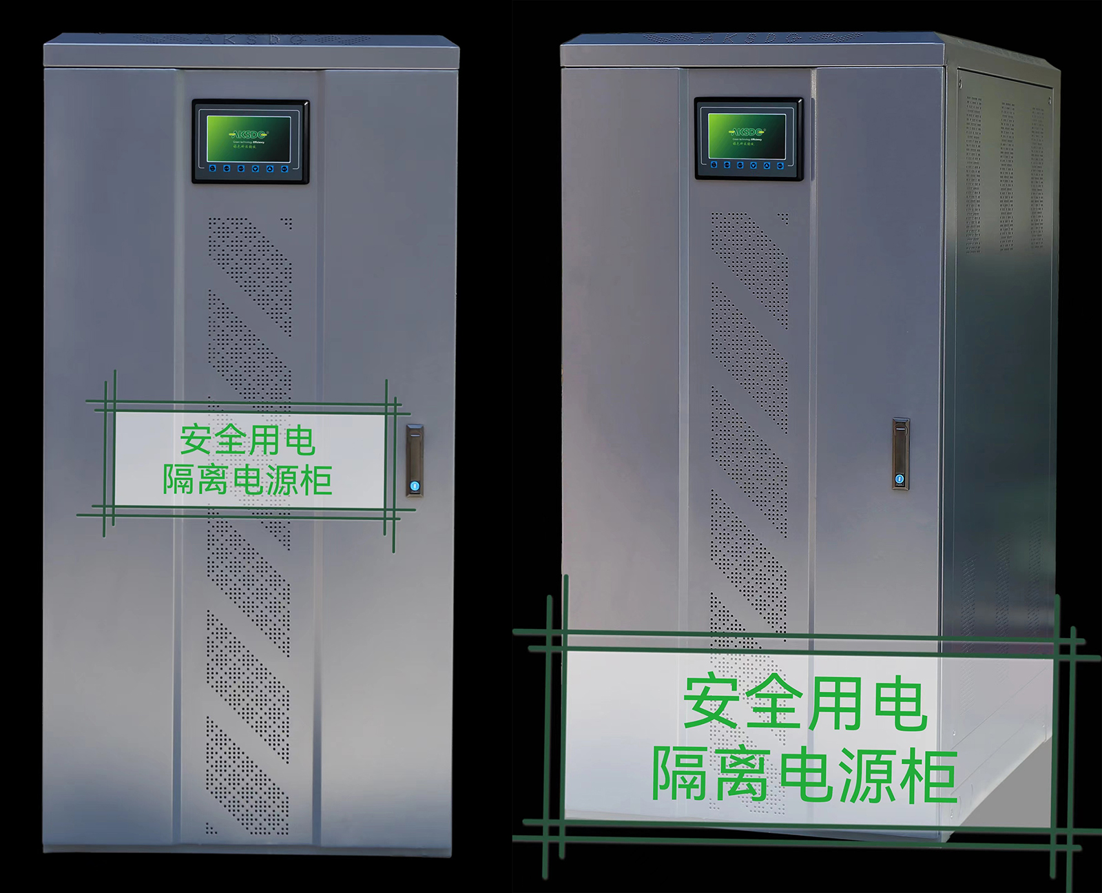
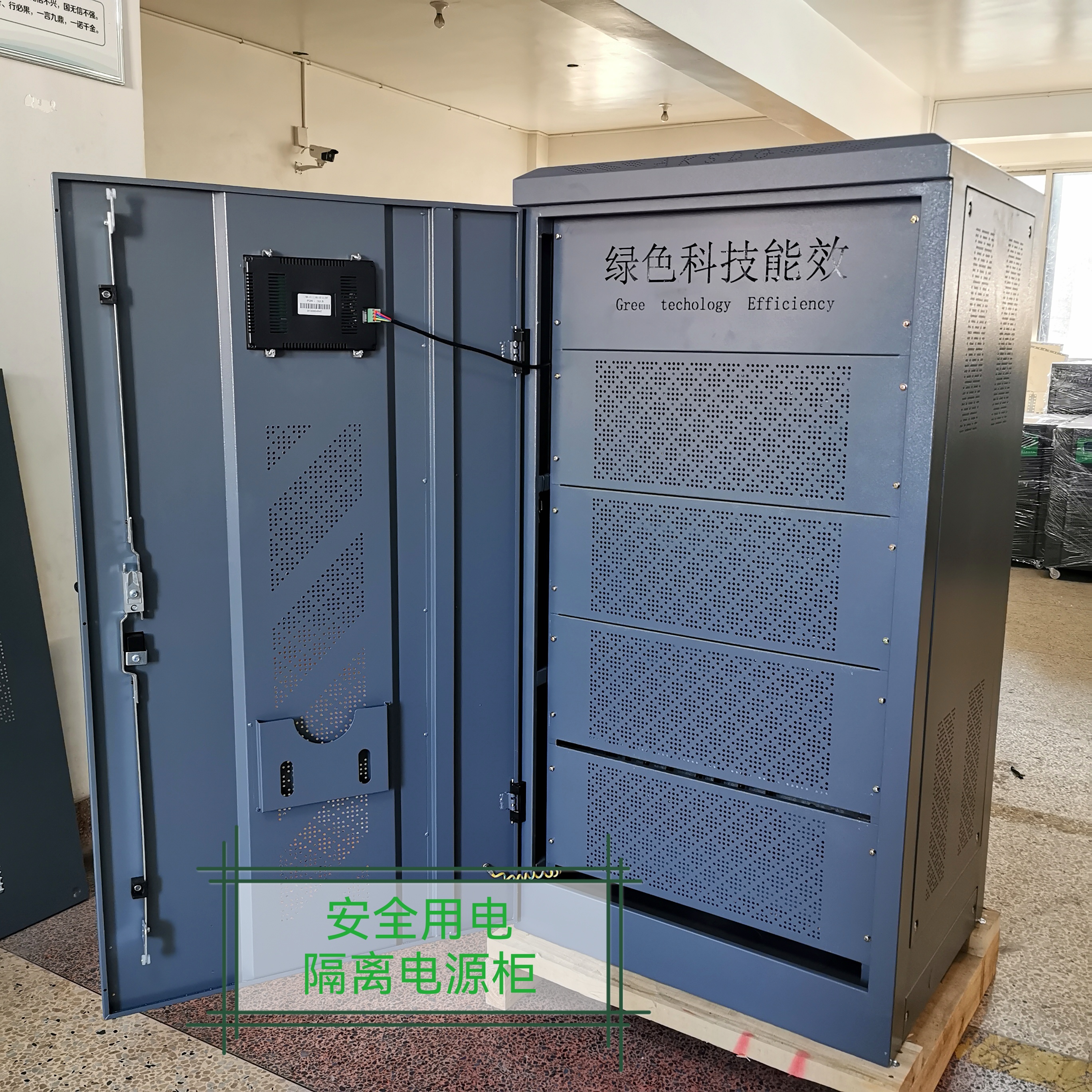
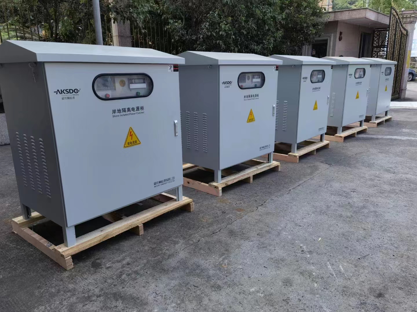
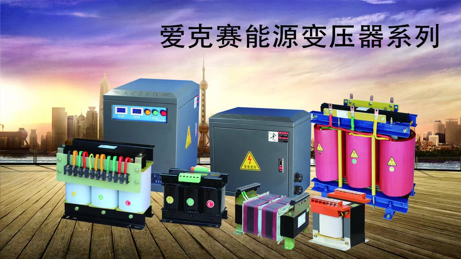
Aikesai energy isolation transformer is a safe power source, widely used in photovoltaic, subway, medical, high-rise buildings, airports, stations, wharfs, industrial and mining enterprises, and tunnels for power transmission and distribution. Safe use of electricity, play the role of protection, anti-interference and anti-filtering.
The principle of isolation transformer is the same as that of ordinary transformer. All use the principle of electromagnetic induction. Isolation transformers generally (but not exclusively) refer to 1:1 transformers. Although the secondary is not connected to the ground, there is still a potential difference and a 180-degree phase difference between any of the secondary wires and the ground, which is dangerous.
The power supply for the control transformer and valve equipment is also an isolation transformer. Power supplies such as tube amplifiers, tube radios and oscilloscopes, and lathe control transformers are all isolation transformers. For example, a 1:1 isolation transformer is commonly used for safety voltage.
First of all, the AC power supply voltage we usually use is connected to the ground with one line, and there is a potential difference of 220V between the other line and the ground. Human contact can cause electric shock. The secondary of the isolation transformer is not connected to the ground, and there is no potential difference between any two lines of it and the ground. People will not get electric shock when they touch any line, so it is safer. Secondly, the output end of the isolation transformer is completely "open circuit" isolated from the input end, which effectively plays a good filtering role on the input end of the transformer (power supply voltage supplied by the grid). Thus, a pure power supply voltage is provided to the electrical equipment.
Another use is anti-interference. It can be widely used in subways, high-rise buildings, airports, stations, docks, industrial and mining enterprises, and tunnels for power transmission and distribution.
Isolation transformer refers to a transformer in which the input winding and the output winding are electrically isolated from each other to avoid the danger of accidentally touching live objects (or metal parts that may be charged due to insulation damage) and the earth at the same time. The same as the dry-type transformer, it also uses the principle of electromagnetic induction, which mainly isolates the primary power circuit, and the secondary circuit floats to the ground to ensure the safety of electricity use.
The main function
of the isolation transformer is to completely isolate the electricity between the primary side and the secondary side, and to isolate the circuit. In addition, the high-frequency loss of its iron core is used to suppress the introduction of high-frequency clutter into the control loop. Using an isolation transformer to suspend the secondary to the ground can only be used in situations where the power supply range is small and the line is short. At this time, the capacitance current of the system to ground is too small to cause personal injury. Another very important role is to protect personal safety! Isolate hazardous voltages.
With the continuous development of the power system, the transformer plays an increasingly important role as a key device in the power system, and its safe operation is directly related to the reliability of the entire power system. Axial and amplitude dimensional changes, body displacement, coil twist, etc. There are two main reasons for the deformation of the transformer coil: one is that the transformer is inevitably affected by external short-circuit faults during operation; the other is the accidental collision of the transformer during transportation and hoisting.
The magnetic flux of the power
transformer core is related to the applied voltage. In the current field, the excitation current does not increase with the increase of the load. Although the core will not saturate when the load increases, the resistance loss of the coil will increase. If the heat generated by the coil cannot be dissipated in time beyond the rated capacity, the coil will be damaged. If the coil is composed of superconducting materials, the increase of current will not cause heat generation. However, there is also impedance caused by magnetic leakage inside the transformer. As the current increases, the output voltage will drop. The greater the current, the lower the output voltage, so the output power of the transformer cannot be infinite. If the transformer has no impedance, then when the transformer flows through the current, it will generate a particularly large electric force, which will easily damage the transformer coil. Although the power is unlimited, it cannot be used. It can only be said that with the development of superconducting materials and iron core materials, the output power of transformers of the same volume or weight will increase, but not infinite! The  nature of
isolation transformers is a safe power supply, generally used for safe electricity, medical treatment, protection , Lightning protection, anti-filtering effect. The primary and secondary voltages of the isolation transformer can be customized upon request. The output end of the isolation transformer is completely "open circuit" isolated from the input end.
principle
The principle of isolation transformer is the same as that of ordinary transformer. All use the principle of electromagnetic induction. Isolation transformers generally refer to 1:1 transformers. Because the secondary is not connected to ground. There is no potential difference between any of the secondary wires and ground. Use a safe power source.
Isolation transformers are not all 1:1 transformers. The power supply for the control transformer and valve equipment is also an isolation transformer. Power supplies such as tube amplifiers, tube radios and oscilloscopes and lathe control transformers are isolation transformers. For example, a 1:1 isolation transformer is commonly used for safety voltage. Isolation transformers are used more often.
Generally, although there is an isolation circuit between the primary and secondary windings of the transformer, in the case of high frequency, the capacitance between the two windings will still cause electrostatic interference between the circuits on both sides. In order to avoid such interference, the primary and secondary windings of the isolation transformer are generally placed on different cores to reduce the capacitance between the two; Electrostatic shielding for high noise immunity.
Electrostatic shielding is to set an unclosed copper sheet or non-magnetic conductive paper between the primary and secondary windings, which is called a shielding layer. Copper sheets or non-magnetic conductive paper are connected to the casing with wires. Sometimes in order to achieve better shielding effect, a shielding shell is also covered throughout the transformer. The lead-out terminals of the windings are also shielded to prevent other external electromagnetic interference. In this way, there is only residual magnetic coupling between the primary and secondary windings, and the equivalent distributed capacitance between them can be less than 0.01pF, thereby greatly reducing the capacitive current between the primary and secondary windings and effectively suppressing the power supply and other circuits. various distractions.
Basic technical parameters of safe electrical isolation power supply
In addition to changing the voltage, the three-phase safe electrical isolation power supply can also electrically isolate the input winding and the output winding from each other to avoid touching live objects (or metal parts that may be live due to insulation damage) and the ground at the same time. danger posed. In addition, the isolation transformer also has a certain function of suppressing various interferences. The isolation transformer belongs to the safety power supply, which is generally used for safe power consumption, medical treatment, protection, lightning protection and anti-filtering. The primary and secondary side voltages of the isolated power supply can be customized upon request. The output end of the isolation transformer is completely "open circuit" isolated from the input end. First of all, the AC power supply voltage we usually use is connected to the ground with one line, and there is a potential difference of 220V between the other line and the ground. Human contact can cause electric shock. The secondary of the isolation transformer is not connected to the ground, and there is no potential difference between any two lines of it and the ground. People will not get electric shock when they touch any line, so it is safer. Axel energy isolation power supply is a safe power supply and is widely used in photovoltaic, subway, medical, high-rise buildings, airports, stations, wharfs, industrial and mining enterprises, and tunnels for power transmission and distribution. Safe use of electricity, play the role of protection, anti-interference and anti-filtering.
1. Frequency of use: 50/60HZ;
2. No-load current: <4%;
3. Withstand voltage: 3000V/min without breakdown; Test instrument: YZ1802 withstand voltage tester (20mA);
4. Insulation class: H (special grade can be customized);
5. Insulation resistance: ≥2MΩ Test instrument: ZC25B-4 megohmmeter <1000V);
6. Connection group: Dyn11; voltage ratio 1:1
7. Allowable temperature rise of coil: 180K ;
8. Heat dissipation method: natural air cooling or temperature control automatic heat dissipation;
9. Noise coefficient: ≤50db(1m)
10, 40℃, relative humidity <80%
12. Altitude: no more than 2500 meters.
13. Avoid exposure to rain, humidity, high temperature, high heat or direct sunlight. There should be a distance of not less than 40cm between the cooling vents and surrounding objects.
14. Avoid working in places with more corrosive liquids, gases, dust, conductive fibers or metal fines.
15. Avoid working in vibration or electromagnetic interference places.
16. Avoid long-term upside-down storage and transportation, and cannot be subjected to strong impact.
17. Wiring method: three-phase five-wire system.
18. Power distribution function: fully intelligent control of safe power consumption, automatic cut-off of power for fault protection; bypass mains/manual automatic.
19. Parameter display function: The isolated power supply screen has the function of displaying operating parameters: input and output voltage, current, phase loss function, and the function of displaying fault information and fault records.
20. Circuit control: adopt digital (CPU) true RMS sampling control system;
21. Protection function: with over-voltage, under-voltage, short-circuit, over-current, reverse phase, lack of equal protection functions, the display screen when the isolated power supply fails Can emit sound and light digital flashing alarm, press any button on the display surface to mute the sound; other requirements (1) Communication interface: with RS232/485, can realize remote control, remote signaling, telemetry, real-time monitoring of working status and parameters, all data It must be set through the display panel, and the communication interface protocol is provided free of charge. 
Method
1. Connect the input terminal of the isolation transformer to the corresponding power supply voltage (1:1), and connect the output terminal of the isolation transformer to the power input of the required equipment. end.
2. Turn on the power and it can be used normally. 
Classification
Ordinary isolation transformers have no direct electrical connection between the primary side and secondary side windings, so general power transformers have the function of potential isolation regardless of the transformation ratio, while isolation transformers can isolate higher potential differences. It is widely used in AC power lines and communication lines to isolate ground loops and effectively suppress common mode interference in the low frequency and audio frequency range, but cannot suppress differential mode interference. Signal and pulse isolation transformers are also widely used in the range of audio to video to interrupt the ground loop and achieve functions such as coupling AC, isolating DC components, and impedance matching. The ground loop impedance is reduced due to the distributed capacitance between the primary and secondary sides of the isolation transformer. When the potential of point B rises and the interference voltage en occurs for some reason, the high-frequency common mode interference can be coupled from the primary side to the secondary side.
The shielding isolation transformer inserts a metal shielding layer between the primary side and the secondary side of the isolation transformer, and the shielding layer divides the capacitance between the primary side and the secondary side into two, which plays a shielding role. If the metal shielding layer is connected to the transformer ground, the common mode interference from the primary side will be bypassed by the shielding layer impedance before reaching the secondary side. If the metal layer is connected to the input terminal of the primary side of the transformer (connect the voltage regulating tap or the ground terminal and the neutral terminal when there is a voltage regulating tap), the differential mode interference from the primary side is also short-circuited by the shielding layer before reaching the secondary side.
Double shielding isolation transformer When common mode and differential mode interference occur on the primary side at the same time, connect one shielding layer to the primary side to reduce differential mode noise, and connect the other shielding layer to the reference plane or ground line of common mode interference to reduce common mode noise. The isolation transformer enclosure is also connected to safety ground. The connection line of the shielding layer must be short and reliable, otherwise the shielding effect will be significantly reduced at high frequencies.
Triple-shielded isolation transformers When higher isolation requirements are required, triple-shielded isolation transformers can be used. The connection method of the three different shields depends on the installation method of the transformer and the grounding conditions. Generally, the transformer is installed on the partition of the equipment rack or the partition wall of the shielding room, and the rack is connected to the safety ground wire of the equipment, and the input power is safely disconnected and protected by an insulating tube.
Requirements for isolation transformers The isolation transformers used in electronic equipment in substations and power plants should be selected with reference to the national standard requirements for equipment. The isolation transformers used in power supplies should meet the following indicators: ① Rated voltage: 220V±20 %; ② Rated current: selected according to the input maximum working current of the equipment plus 50%; ③ Insulation resistance: >10M Ω; ④ Power frequency withstand voltage: 2500 V, 1 min, leakage current <10mA; ⑤ High frequency interference suppression : Common mode 2500 V (1 MHz damped oscillation wave) rejection >60 dB, differential mode 1250 V (1 MHz damped oscillation wave) rejection >40 dB. The magnitude of the leakage current of the isolation transformer and the shielding effectiveness should be selected according to the needs of different equipment applications. 


